EN 60204-1 is the fundamental standard for electrical equipment on machinery. It does not apply to a single component or a single area, but to the entire electrical system of the machine: from the power supply connection point, through electric shock protection and control circuits, right through to markings, documentation and acceptance tests. Therefore, treating it as a standard ‘from the emergency stop’ or ‘from the control cabinet’ misrepresents the issue from the outset.
This is precisely where the most common interpretation issue arises. EN 60204-1 sets out the electrical safety requirements for machinery, but it does not replace standards covering functional safety, guards, safety distances or a comprehensive risk assessment. It works well when read as the electrical framework for the entire machine, rather than as a standalone document intended to cover all safety requirements.
What does EN 60204-1 actually regulate?
The standard covers electrical, electronic and programmable equipment on machines that is not portable during operation. Its scope begins at the point where the power supply is connected to the machine. This is an important distinction, as EN 60204-1 does not cover the entire building installation or the plant’s infrastructure. It applies to what happens from the point where the power supply enters a specific machine or group of machines.
The voltage range also sets the limits quite clearly. We are talking about equipment rated up to 1000 V AC and up to 1500 V DC, at frequencies up to 200 Hz. If the installation falls outside this range, other documents must be consulted. The same applies when special applications are involved, such as machinery for use in explosive atmospheres, mining machinery, or equipment for which separate parts of the 60204 series have been developed.
This means that EN 60204-1 is not a standard that covers ‘everything with wires’. It is a standard for the electrical equipment of industrial machinery within a fairly precisely defined scope. And that is precisely why it is so useful: it does not attempt to cover the entire field of engineering, but rather organises precisely that part which deals with the electrical systems of machinery.
Where does her role end?
This is one of the things that needs to be clarified straight away, as otherwise it is easy to form a misleading impression of the standard. EN 60204-1 does not cover all machine-related hazards. It does not, on its own, address issues such as guards, safety functions rated at PL or SIL levels, safety distances, ergonomics, the organisation of risk zones, or a comprehensive risk assessment.
From a machine design perspective, this has very specific implications. It is possible to have electrical systems that comply with EN 60204-1, yet still have a machine that does not meet the requirements of the overall safety system. The reason is simple: electrical safety is just one layer. Sometimes it is the dominant one, but it is still just one.
In practice, this is where most misunderstandings arise. The design is ‘compliant with EN 60204-1’, so some people assume that the safety aspect has been dealt with. It hasn’t. The electrical aspects have been sorted out. That’s a lot, but it’s not everything.
How does EN 60204-1 relate to other standards?
It is easiest to think of this standard as a document that organises the electrical framework of a machine. Alongside it, there are standards covering other layers. IEC 62061 and ISO 13849-1 deal with the functional safety of control systems. ISO 13850 describes the principles of emergency stop functions. IEC 60364 covers electrical installations in buildings. When these levels become confused, design errors begin to occur.
| Standard | Main area | What it does not replace | The role of the machine in the project |
|---|---|---|---|
| EN 60204-1 | the machine’s electrical components | a comprehensive risk assessment and safety functions | organises the machine’s electrical system, from the power supply to the output |
| IEC 62061 | safety-related control systems, SIL | the electrical requirements of all the machine’s equipment | is used to assess functional safety |
| ISO 13849-1 | SRP/CS, Performance Level | installation and safety requirements of EN 60204-1 | describes functional safety at PL level |
| ISO 13850 | emergency stop as a safety feature | the complete electrical architecture of the machine | sets the rules for emergency stopping |
| IEC 60364 | building electrical installations | requirements for the machine’s electrical equipment | refers to the power supply infrastructure outside the machine itself |
The key takeaway from this table is simple. EN 60204-1 does not compete with these standards. It occupies its own niche. If a designer attempts to use it to replace IEC 62061 or ISO 13849-1, they quickly lose sight of the safety level of the function. If, on the other hand, they overlook EN 60204-1 because they focus exclusively on PL and SIL, they may build a system that is logically correct but electrically weak or unreliable.
Scope of the standard’s requirements – from the power supply input to the acceptance test
The structure of EN 60204-1 is very logical. It begins with power supply and isolating devices. It then moves on to protection against electric shock, protection of equipment and bonding. Next come control circuits, operator controls, cabling, instrumentation, marking, documentation and, finally, verification.
This is significant because it illustrates the standard’s underlying logic. It is not a collection of independent clauses that can be ticked off in any order. It is a design pathway. First, one must understand how the machine is powered up and shut down. Then, how it behaves in the event of a fault. Next, how the control circuits and stop functions operate. Finally, there remains the question of whether all this can be tested, documented and safely maintained.
A well-designed machine usually shares one common feature: the orderliness of the documentation mirrors the orderliness of the design itself. Where the design takes shortcuts, the standard starts to ‘cause problems’, because it suddenly becomes impossible to answer unequivocally where the power supply circuit ends, what the disconnection logic looks like, or which wires form the actual protective circuit.
Power supply, disconnection and protection against unintended start-up
This is one of the most important sections, although it is rarely discussed in detail outside the context of switchboard design. The standard begins with the power supply connection, input terminals, the connection point for the protective conductor, and the main isolating device. This layout alone shows that it is not just a question of ‘whether there is power’, but whether the machine can be disconnected from the power source clearly and safely.
This area also covers devices designed to prevent unintended start-up and the measures required for safe servicing. This is not an organisational matter to be left until later, but rather a key aspect of compliance with the standard. If a machine lacks a sensibly designed disconnection mechanism, a service lock or logic to prevent unexpected restart, this will very quickly become apparent during inspection, maintenance or in the event of a breakdown.
This is precisely where the difference lies between a machine that ‘works’ and one that can be safely stopped, disconnected, secured and restarted. In many factories, the problem is not a lack of components, but poorly designed logic for stopping and restarting. EN 60204-1 sets out this subject very clearly.
Electrical safety – not just PE and the enclosure
The standard distinguishes between basic protection and protection against faults. This is important because all too often the issue is reduced to the simple assertion that ‘there is a protective conductor, so everything is fine’. It isn’t. You also need to know how the system behaves in the event of insulation failure, how automatic power cut-off works, what the conditions are for accessible conductive parts, and in which circuits PELV-type solutions are used.
This means that protection against electric shock is not a single measure, but a system of interdependent factors. What matters is the type of power supply, the selection of protective devices, the short-circuit loop impedance, the continuity of protective conductors, the method of connecting enclosures, and the behaviour of the circuit under fault conditions. If any of these elements is neglected, the entire protection system becomes ineffective.
In technical inspections and audits, this area is one of the most objective. There isn’t much room for interpretation here. Either the protective circuit is continuous and tested, or it is not. Either the conditions for protection by automatic disconnection are met, or they are not. This is precisely why this section of the standard so clearly distinguishes between machines designed with due care and those that are merely ‘cobbled together electrically’.
Equipotential bonding – a topic you don’t notice until there’s a problem
Protective bonding is one of those elements that seem obvious in a machine that works properly. The problem only arises when continuity is poor, the connection has been made haphazardly, or someone has assumed that the frame ‘conducts anyway’. The standard leaves no room for discretion here. The protective bonding circuit must be designed deliberately, with guaranteed continuity, correct connections and appropriate cross-sections.
This is particularly important in systems with higher leakage currents, featuring inverters, EMC filters and complex power electronics. In such cases, bonding ceases to be a purely formal requirement and becomes one of the prerequisites for the predictable behaviour of the entire machine. A poorly designed or poorly executed protective bonding system can cause not only safety issues, but also functional and diagnostic problems.
| Area | What needs to be provided | A common mistake | Result |
|---|---|---|---|
| Basic protection | no access to live parts | too easy access, inadequate guards | immediate risk of electric shock |
| Protection in the event of damage | effective disconnection or other protective measures | no comprehensive analysis of failure conditions | ineffective system response in the event of a failure |
| Protective bonding | a continuous protective circuit | accidental connections or poor continuity | unreliable protection and damage that is difficult to detect |
| PELV | proper isolation and circuit parameters | confusion with a low-voltage control circuit without full isolation | illusory protection and design flaws |
The table clearly shows that most problems do not stem from the absence of any single component, but from the mistaken assumption that a few loosely compliant elements will automatically form a safe system. EN 60204-1 is designed to prevent precisely this. It requires a holistic approach, rather than a piecemeal one.
Protection of electrical equipment – overcurrent, overheating and short circuits
The standard does not only protect people. It also protects the machinery itself. This is important because damage to equipment, cables, transformers or drives very quickly becomes a hazard to people and to the process. That is why the sections on protection against the effects of overcurrent, short circuits and overloads are just as important as those on electric shock.
More recent editions of the standard place greater emphasis on short-circuit current rating, overcurrent protection and protection coordination. This is no coincidence. In modern machinery, the proportion of converters, drives, filters and complex control systems is increasing. If their short-circuit withstand capacity, power supply conditions and protection logic are not calculated as a single system, gaps arise which cannot subsequently be ‘closed’ simply by changing a single circuit-breaker.
It is very often here that the difference becomes apparent between a design drawn correctly on a diagram and a circuit that is actually ready for safe operation in a plant. A short circuit, overload or single-phase failure do not test the specifications, but the actual protection circuit.
Control circuits and control functions – where electrical systems end and safety logic begins
EN 60204-1 covers control circuits, control functions, stop functions, protective interlocks and the behaviour of circuits in the event of a fault. This is a very broad scope. However, one must be mindful of the limits of interpretation. The standard organises the electrical control architecture of a machine, but does not itself specify the safety level of functions in terms of PL or SIL.
This distinction is crucial. It is possible to have a stop circuit or interlock that is correctly designed in accordance with EN 60204-1, yet still fail to demonstrate the required level of functional safety. This is precisely why two separate considerations must be addressed in machine design. Firstly: is the circuit electrically sound? Second: does the safety function meet the required level of reliability?
In reality, a good design addresses both. A poor one addresses only one of them. Then a typical problem arises: someone says that ‘the safety system is complete’, when in fact they have merely sketched out a relay or a safety controller without fully justifying the entire function.
Stop functions, emergency stop and emergency shutdown – these should not be lumped together
This is one of the most commonly misunderstood parts of the standard. A ‘stop function’, ‘emergency stop’ and ‘emergency switching off’ do not mean the same thing. A normal stop may operate on a different logic to an emergency stop. An emergency stop is a safety-related function designed to halt movement or a process. Emergency switching off refers to the immediate disconnection of the power supply due to an electrical hazard.
These differences are not merely theoretical. They have a direct bearing on the design. Not every red button performs the same function. Not every stop function should cut off power in the same way, nor does every emergency situation require an identical response from the machine. If these roles are confused, the result is either overly aggressive disconnection, which damages the process and components, or an overly gentle response where immediate shutdown was required.
| Function | What is it for? | What not to confuse |
|---|---|---|
| Stop function | normal or controlled deceleration | is not automatically an emergency stop |
| Emergency stop | safety-related emergency stop | does not always mean that the power supply has been completely disconnected |
| Emergency shutdown | rapid disconnection of power in the event of an electrical hazard | it isn’t simply a ‘stronger E-STOP’ |
This passage in particular illustrates very clearly that EN 60204-1 is not a standard based on individual machines, but rather on the logic behind a machine’s electrical behaviour. Functions that appear similar from the operator’s perspective may serve a completely different purpose from an engineering perspective.
Operator interface, labelling and layout clarity
Good electrical design in machinery is not merely about correct wiring diagrams. It must also be intuitive to use. That is why the standard addresses colours, markings, control devices fitted to the machine, indicator lights, buttons and enabling devices. These are not merely aesthetic elements or ‘ergonomic extras’. Incorrect markings and unclear signal indicators increase the risk of operator error and complicate maintenance.
In an industrial setting, this is of great importance. In the event of a breakdown or changeover, what matters is not only whether the system is functioning, but also whether its status can be quickly identified. Ambiguous terminology, inconsistent colour coding and a lack of order in labelling mean that even a technically sound machine becomes difficult to operate safely.
This is one of those areas that tends to be overlooked because it doesn’t immediately result in spectacular failures. Instead, it leads to recurring minor errors, oversights, longer response times and an increased risk in non-routine service situations.
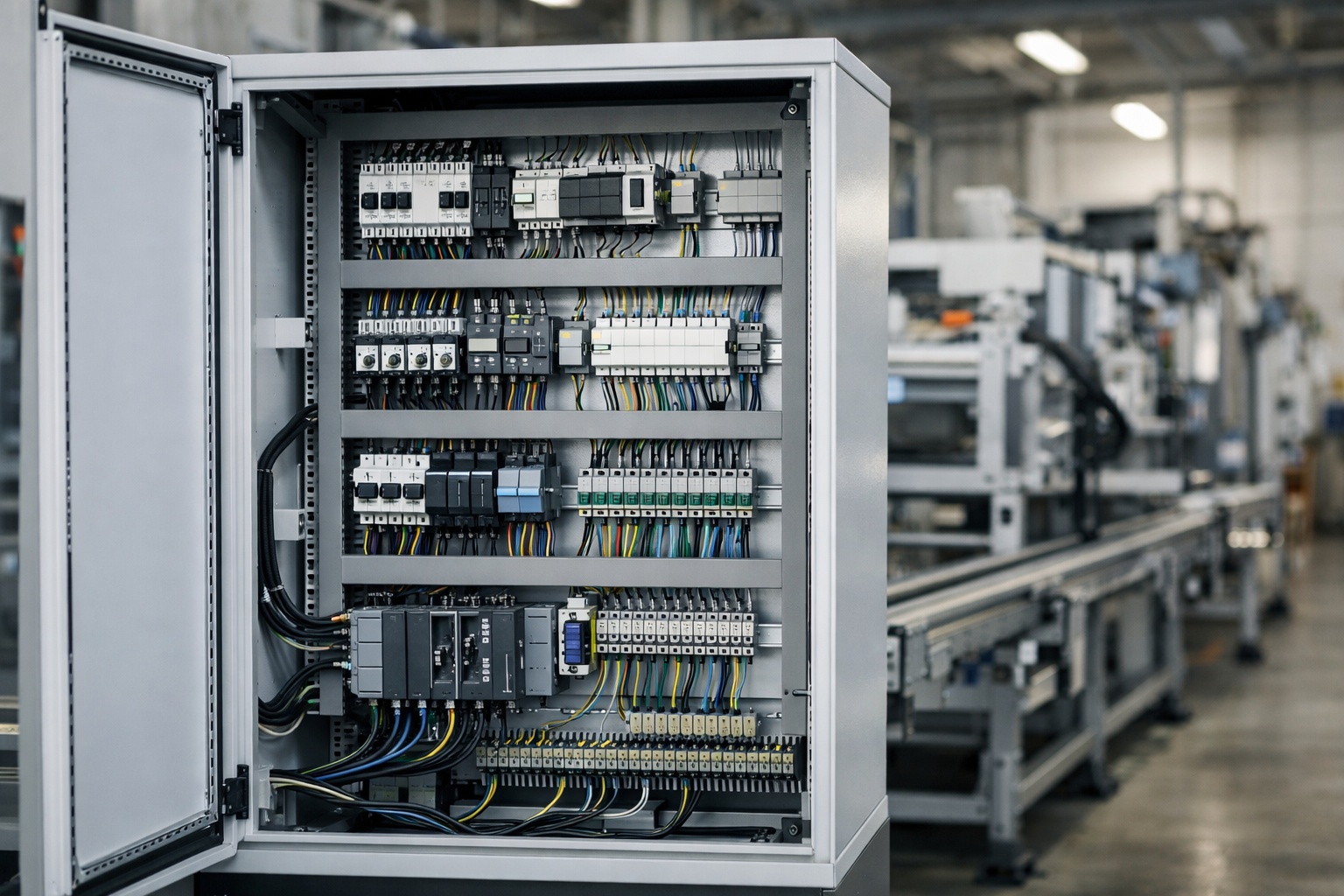
Cables and practical application – where theory meets reality
EN 60204-1 also covers the aspects of wires, cables and cabling practices. This is very important, as compliance with the standard does not end with the circuit diagram. The way wires are routed, their identification, functional separation, mechanical protection, the selection of cross-sections, and the organisation of connections within the control cabinet and on the machine are all significant factors.
During the prefabrication and installation stages, a number of errors arise that are not apparent from the documentation alone. Poor routing of control cables alongside power circuits, untidy cable trays, poorly labelled terminals, and illegible changes made ‘in a hurry’ – all of these factors reduce the quality of the system and can sometimes directly compromise safety.
A well-designed and well-built machine is easy to understand. This is evident in the wiring just as much as in the diagrams. If the installation looks chaotic, it is usually not just an aesthetic issue.
Technical documentation – without it, the machine becomes difficult to maintain safely
The standard also covers technical documentation and reference designations. This is very important, as documentation is not merely a formality. It is an integral part of safe operation. Schematics, equipment markings, terminal identification, circuit descriptions and service documents determine whether a machine can be safely diagnosed, modified and maintained.
This is where many problems arise. The machine is running, but no one apart from its designer understands the logic behind the connections. Changes made during commissioning are not reflected in the final documentation. The labelling in the control cabinet does not match the diagram. As a result, every breakdown and every intervention becomes more risky.
Good documentation is therefore neither a luxury nor a mere formality. It is one of the prerequisites for ensuring that the safety measures designed at the outset can be maintained throughout the machine’s service life.
Verification – or how the standard requires compliance to be confirmed
EN 60204-1 does not stop at design requirements. It also requires verification. This is one of the strongest aspects of this standard, as it transforms it from a document describing ‘how things should be’ into one that requires verification that this is indeed the case.
Key areas of verification include the continuity of the protective bonding circuit, automatic shutdown conditions, insulation resistance, voltage tests, protection against residual voltages, and functional tests. This means that accepting the machine is not simply a matter of checking that the switchboard is powered up and all the lights are on. It must also be confirmed that the protective measures and functions are operating as intended.
| Test area | What is to be confirmed | Where does the problem usually arise? |
|---|---|---|
| Bonding continuity | the effectiveness of the protective circuit | mechanical connections, bridges, assembly modifications |
| Insulation resistance | the condition of the insulation and the absence of unwanted leakage | wires, moisture, installation faults |
| Protection against residual voltage | safe behaviour after power is disconnected | drives, converters, energy storage systems |
| Functional tests | the correct functioning of the system’s functions and responses | control logic, stop functions, interlocks |
The main point of this chapter is simple. The standard is not satisfied with a design ‘on paper’. It requires proof that the finished machine behaves as intended. This is a very practical approach, as it is precisely at the acceptance stage that discrepancies between the specifications and the actual condition of the system come to light.
The most common misinterpretations
The first mistake is treating EN 60204-1 as the sole machine safety standard. The second is reducing it to an emergency stop. The third is confusing an emergency stop with emergency switching off. The fourth is neglecting bonding and continuity tests. The fifth is overlooking the boundary between the building installation and the machine’s electrical system. The sixth is the assumption that, since the control system looks ‘safe’, the issue of PL or SIL is settled.
In projects and audits, these errors do not usually occur in isolation. They tend to go hand in hand. One person oversimplifies the role of standards, another fails to finalise the documentation, and the end result is a machine that works but cannot be clearly assessed or safely maintained.
The biggest problem is that many of these errors do not immediately lead to a spectacular failure. Instead, they degrade the quality of the entire system. And this is precisely what is hardest to detect without a robust standards framework.
Summary
EN 60204-1 is the fundamental standard for the electrical safety of industrial machinery, but its strength does not lie in any single requirement. Rather, it lies in the fact that it organises the entire electrical system of the machine, from the power supply input to the final load. When properly applied, it does not simply result in a ‘standard-compliant cabinet’, but rather a system that can be safely powered, stopped, serviced, diagnosed and accepted.
The biggest mistake is trying to treat it as a one-size-fits-all standard, or conversely, reducing it to a few points about the emergency stop. Neither approach captures its true role. It is a document that organises a machine’s electrical system, but it requires coordination with other standards and a proper risk assessment. If one had to sum it up in a single sentence, the most accurate way would be this: EN 60204-1 does not replace the entire safety of the machine, but without it, it is difficult to speak of truly organised electrical safety in an industrial machine.
Sources and materials:
https://webstore.iec.ch/en/publication/26037
https://cdn.standards.iteh.ai/samples/18875/90805b617b194c79a353f317536a34d5/IEC-60204-1-2016.pdf
https://www.iso.org/standard/59970.html